- 1.Automatic Rotor Controller
- 2.Automatic Slip Regulators
- 1.Sugarcane Crusher and Mixer
- 2.Sugarcane Fibrizor and Shredder
- 3.Choppers and cutters
- 4.Leveller
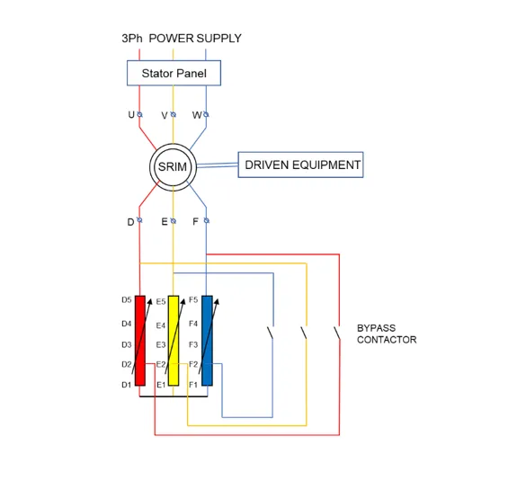
Slip ring motors require a high starting torque, and require additional starters. This is achieved by connecting additional starting resistances while starting the rotor circuit. As a result, we require starters that operate on full motor voltage and high starting torque. External resistance is added through slip ring of the motor which restrict the starting current & boost torque to drive various applications.
We have two models in Slip ring starters :
Both models are used for different applications, but work on the principle of varying the rotor frequency with the magnetically amplified resistance.
Automatic Slip Regulators are preferred for Sugar Industry applications such as Fibrizor, Crusher, Chopper, Cutters and Levellers.
Automatic Rotor Controllers on the other hand are preferred for applications like Pumps (Centrifugal, Vertical turbine, Mixed flow, Oil hydraulic), Compressors (Centrifugal, Reciprocating, Process Compressor, Refrigeration, Screw, Air-conditioning) and heavy equipment (Ball Mill, Crusher, Fans) etc.
Automatic Slip Regulator
The automatic slip regulator, commonly known as ASR, are slip ring regulators that automatically vary the resistance in response to the rotor frequency of the motor. This is done primarily to allow for higher torque when motor load increases. In sugar industries, this application is preferred as it helps vary the motor torque when the kicking load increases. This application has been applied all over India for sugar industries.
The applications include:
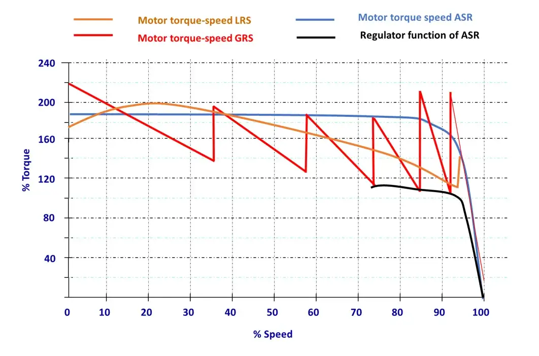
When the motor is loaded for more than 100%, then the buffer resistance is amplified automatically for a short time for about 10-15% of the load. When the load is less than the 100% of its rated capacity, the slip regulator offers up to 4% of its buffer resistance as load levels are at rated value, thus allowing for higher speed application. Not only does it allow for higher motor speeds at lower torque, it also allows for significant energy savings. Unlike the rotor controller, the automatic slip regulator stays in series with the motor to provide the required torque as opposed to the rotor controller which is bypassed after the motor reaches full speed.
Following is a technical explanation of the working of the Automatic Slip Regulator.
During variable load (Kick load) ASR responds naturally. ASR is designed in such a way that ASR resistance offered is dependent on rotor frequency. The governing equation of ASR resistance is
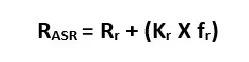
RASR = ASR resistance at any frequency
Rr = Residual ASR DC resistance (very low value –typically 3%)
Kr = Resistance amplification factor
fr = Rotor frequency
When Motor Starts with ASR, at zero speed the rotor frequency is 50HZ & resistance offered by ASR is maximum. This value is decided by the following equation
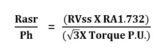
where RASR / Ph = equivalent star resistance of ASR at any frequency in Ohms.
RVSS = Line to line Rotor voltage at standstill in volts.
RA = Rotor current at full load in Amps.
Torque P.U. = Motor torque (per unit value) desired at standstill
Thus, ASR resistance varies with motor slip, automatically & stepless. The motor and driven equipment thus reach full speed steplessly.
Torque speed curve comparison for Various Starting Systems